


When it comes to electromechanical switches, there are various forms of switch terminals that can be used to connect the circuit to the switch to ensure correct functionality. One of the most common forms is the solder lug terminal used in panel mount switches, but how do you go about figuring out how to solder switches?
The switch is fitted with lugs, generally found on the underside of the switch, and wire is then soldered to the lugs to form a solid connection through which electricity can pass. Since this process of forms a permanent connection between the switch and the wire, solder lug terminals are reliable and the best solution for high current loads.
Types of Soldering
There are two common types of soldering: Straight (Class 1) and J-Hook (Class 2 and 3). Both processes begin the same way with striping the insulation off the wire and then tinning the conductor, but while the Class 1 solder is a straightforward process of soldering the wire to the terminal, the J-Hook requires the wire to be bent and threaded through the hole before soldering. This creates a stronger bond to the terminal and is perfect for applications where a failure could prove critical.
Class 1 Soldering (Straight)
Class 2 and 3 Soldering (J-Hook)

Recommended Soldering Guidelines
Most contamination problems can be prevented by exercising care during the cleaning and soldering process. Care should be taken not to immerse or spray unsealed switches during flux removal. Contact E-Switch for specific soldering recommendations and specifications not found in this blog post. Generalized soldering procedure are outlined below.
Hand Soldering and Temperatures
Recommend soldering irons of 30 watt maximum with a tip temperature of 345°C (650°F) for 2-3 seconds and solder of 0.030 – 0.040 diameter. Soldering times and temperatures shouldn’t exceed the recommended ranges of the specific switch Series. Do not operate switches during or immediately following soldering (within one to two minutes) as it could lead to the melting of resin components.
SMT Reflow (Lead and Lead-Free)
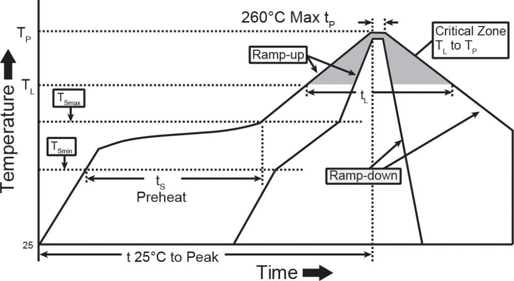
“Typical” SMT Reflow (Pb and Pb-Free)
| Profile Feature | Sn-Pb Eutectic Assembly | Pb-Free Assembly |
| Average Ramp-Up Rate (TSmax to Tp) | 3°C/second max. | 3°C/second max. |
| Preheat -Temperature Min. (TSmin) -Temperature Max. (TSmax) -Time (tSmin to tSmax) | 100°C 150°C 60-120 seconds | 150°C 200°C 60-180 seconds |
| Time maintained above: -Temperature (TL) -Time (tL) | 183°C 60-150 seconds | 217°C 60-150 seconds |
| Time within 5°C of actual Peak Temperature (tP) | 10-30 seconds | 20-40 seconds |
| Ramp-Down Rate | 6°C/second max. | 6°C/second max. |
| Time 25°C to Peak Temperature | 6 minutes max. | 8 minutes max. |
Classification Reflow Profile
Wave Solder Time and Temperatures
When wave soldering, we recommend using a no-clean flux soldering process, rather than a process that requires washing. The fluxing process must be controlled so as not to have flux migrate inside the switch.
Wave Solder
(Includes Pb-Free, max. component side preheat temp-130°C)
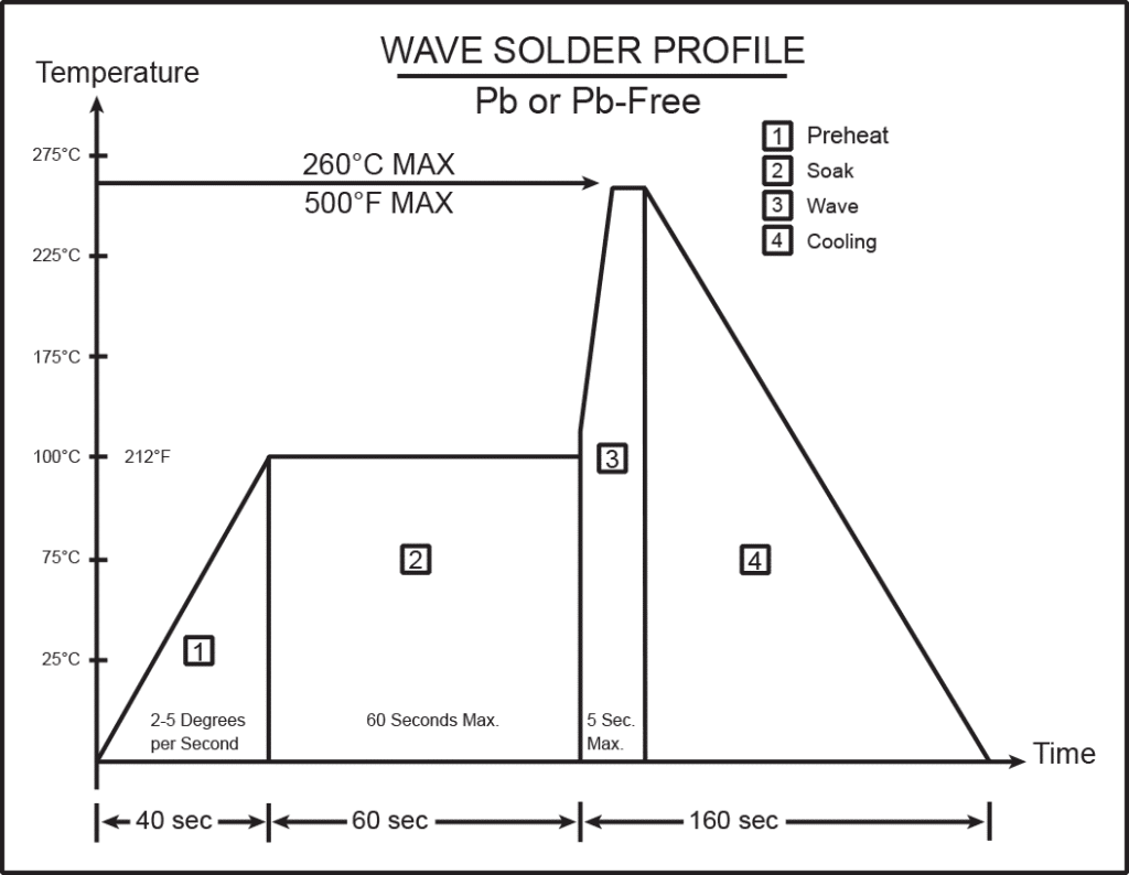
Good venting is required. No-clean flux vapors can enter the switch if adequate venting is not available. The vapors will condense on the internal contacts and become an insulator when they solidify.
- Preheat temperature/time: Circumferential temperature of the P.C. Board not to exceed 100°C (212°F) for 60 seconds.
- Soldering temperature/time: Not to exceed 260°C (500°F) for 5 seconds.
Terminal Shrink Tubing
It’s not always possible to add shrink tubing, but covering the solder joint with it protects from debris that could lead to corrosion while also reducing strain. An epoxy seal on the bottom of the switch is another way to add further protection.